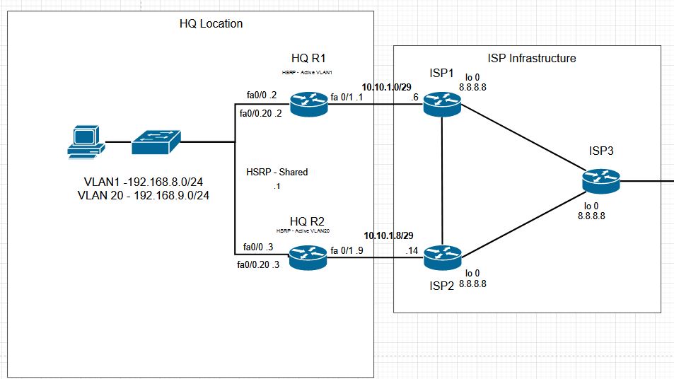
CCNP Topology Configuration HQ
The HQ set up will cover our basic IP addressing, NAT, default routes, HSRP, and IP SLA Tracking. None of the set up should be considered as best practice, but as a way to demonstrate specific topics related to networking. In an actual network there are many other considerations to take into account, but we can demonstrate concepts and configurations.

Initial ISP Requirements
Because we need our HQ routers to interact with the ISP infrastructure we need two items configured. First, we need the /29 networks configured on ISP router 1 and 2. Next, we will put a loopback interface on each router for IP SLA Tracking.
Both ISP1 and ISP2 will be set up similarly for now. The summary of the IP addressing is shown below. With this minimum infrastructure in place, we can move on to the HQ site.
ISP1


ISP2


HQ Site Initial Configuration
HQ R1 ISP Network and Default route
Starting with the HQ R1, we need to configure our initial external connectivity to the ISP1. This requires the /29 subnet to be added onto the Fa0/1 interface, and a default route to be added. After adding that configuration, we can do our initial verification ISP connectivity.
Here we can see the initial subnet is configured, and we have added the default route. Checking the routing table shows the static route, and if we ping the ISP gateway or the ISP loopback, we get a response.

HQ R1 inside networks and NAT
We use the native Fa 0/0 interface for the first network, and create a dot1q sub-interface for the VLAN 20. Under each interface we also add the ip nat inside command. The ip nat outside command has to be configured on interface Fa 0/1 towards the ISP as well.

To enable communication from our inside networks (that the ISP won’t know about), we set up a NAT overload to the outside interface. For this we are going to use a simple NAT statement and a single access list. For cases where we had multiple ISPs on the single router, we would want to use a rout-map for the NAT, but it isn’t needed here.
The access list identifies all IP traffic from our inside networks going to any destination. The NAT statement indicates that we use an access list for our source, and will translate the inside addresses to a PAT, so that multiple inside addresses can use the same external IP.

For verification that our set up is working we will send traffic from each inside interface to our ISP loopback. Then verify a response and the NAT translation.
We can see that we got a response and that our inside local addresses were translated to the inside global address. The outside destination remains the same.

HQ R2
The initial set up of R2 will be similar to the R1, but on the inside interfaces we will use the .3 address for the interface. On the outside we have a different /29 network for the ISP, but in general the set up is the same.
Our HSRP Setup
For our circumstance we don’t have layer 3 switching on the inside network, so we need an alternative to stacked switches or VSS for providing gateway redundancy. We will start off with HSRP, and then demonstrate other options later.
We will setup HSRP, so that our first network uses ISP1 for forwarding, and VLAN 20 will use ISP2 for forwarding. In order to control this, we will use the HSRP priority so that R1 answers for one network, and R2 answers for the other. In addition, we will set up IP SLA tracking to the ISPs so that if an ISP fails the primary router will decrement its priority and allow the other router to take over forwarding.
R1 HSRP Settings
Below we can see that each router uses the standby commands for HSRP setup. The Standby IP will be the IP address that is shared between devices, with the higher priority device responding.
Timers are set for triggering fail over events in case of a router hardware failure, and IP SLA tracking is configured for failover in case we lose connectivity to an ISP.
For the router that is to be the primary forwarder for a given subnet, we also used the preempt key word so that in the case that the primary device comes back online or recovers from an ISP failure, it takes over forwarding duties again.

R2 HSRP Settings

IP SLA Tracking
Each router, R1 and R2, will be set up to track the ISP loopback at 8.8.8.8. If it loses the ability to connect to that address primary HSRP forwarding router will lose enough priority to initiate the failover.

Verification of the basic HSRP setup can be seen below showing that R1 is active for the first network, and standby for the VLAN 20 network. It also lets us know that R2 is standby for the first network.


As an additional verification we break connectivity from R1 to the ISP 1, and verify that R2 takes over forwarding for both networks.
We can see that R1 did decrement its priority and is now in the standby for both networks.

Here R2 has now assumed active forwarding for both networks.

Summary
We set up basic addressing on the ISP equipment so that we had something for the HQ routers to connect to, and then set up basic HQ equipment IPs, static routing, NAT, and HSRP using both ISPs for forwarding. Then we finished up by making sure if we had an ISP outage forwarding changed to the standby router.
